
While I talk about the role that carbon monoxide poisoning can play in the experience of paranormal activities and hallucinations, I don’t actually use the kit on stage. I doubt it would make for a very exciting element of the show; with most venues being pretty hot on environmental safety and building maintenance these days.
So why are we talking CO meters at all? Without being disparaging, some of the experiences associated with paranormal activity are similar to those experienced during carbon monoxide poisoning; delirium, hallucinations, fast heart rate, and confusion. Who is to say in the middle of the darkest night, deep in a creepy old building, that the image you see flash across your vision isn’t the product of something rational? Nor would you be the first!
We’ve known about this phenomenon for over a century. Science journal, May 9, 1913 reports the account of ‘An Investigation of a “Haunted” House’. It describes the manifestations of the hauntings within the house, and then provides the reason. It’s open access, so you should be able to read it here for free.1
So carbon monoxide poisoning could explain some experiences, and as a scientist with an interest in why we perceive rational things as paranormal, you can probably see why I’m an advocate of these simple bits of kit. So why don’t we see CO meters on ghost hunt shows? Is it because it would ruin the show if ‘the unexplained’ could be easily explained? But to be proper investigators, EVERY ghost hunter should be using it on EVERY vigil. Anyway, long story, short, mine looks like this:

However, buying a nice, shiny one is not the only way to do this. So if the last project whet your appetite for some coding and Arduino-based DIY fun, then you will like this one too. So, just like before, here is how to make one and programme your shiny new Arduino. First the shopping list.
Stage 1: The Shopping List
Maybe you’ve already got your Arduino, but if you haven’t, see the first item on the shopping list for making the ‘Spirit Box’. Again follow the notes there to ensure you get the right leads to attach the Arduino to your computer. If you got all that last time, you’ll already have jumper leads. If not, get them too.
You’ll need a sensor for carbon monoxide. It’s an MQ-7 CO sensor. Costs about £4 from your usual ‘online retailer’ or local store. There are many brands available, and they all look similar. Just get the one you fancy.

You want a TMB-12A buzzer. They are small buzzers that run on something between approximately 4 and 7 volts. Expect them to only cost about 50p each, but you’ll probably end up buying 10 of them as they are often sold that way.

I didn’t talk about breadboards in the last project, but it may come as no surprise that I do so now, as they are common in DIY electronics prototyping. Chances are, if that’s your bag, you’ve likely got one and used it already. There’s no soldering required; just plug in the jumpers to make the connections. The + and – rails down each side, run the length of the board, and the rows labelled a to e run horizontally on each side, as do f to j. Yours might not be labelled though. Don’t worry, the layout inside is the same.

Stage 2: The Hardware Assembly
Usual disclaimer stuff: BUILD AT YOUR OWN RISK. The components you will be assembling and using carry live electric current, contain small parts, and may be sharp. If you aren’t confident in handling the risk in any aspect of this, ask someone for help. We’re also going to introduce the element of fire in this project, so extra care is required.
The hardware build is really easy. Start by wiring up the buzzer. Using the jumper leads and breadboard, connect the following pins:
- Buzzer – to Arduino GND using black wire.
- Buzzer + to Arduino D8 using white wire.
Notice how the breadboard works here. The horizontal strips inside the board make the connections between the buzzer and the wire.
Note that the breadboard pictured here does not have the ‘power rails’ that run the length of the board. (The images used for this post are sourced from the video made by Creative A. It is very short, and lacks the information included here. I hope this post allows you to work at a more considered pace.) As long as you mount the components in a similar orientation to the image, and not in any power rails you might have, you will be fine.

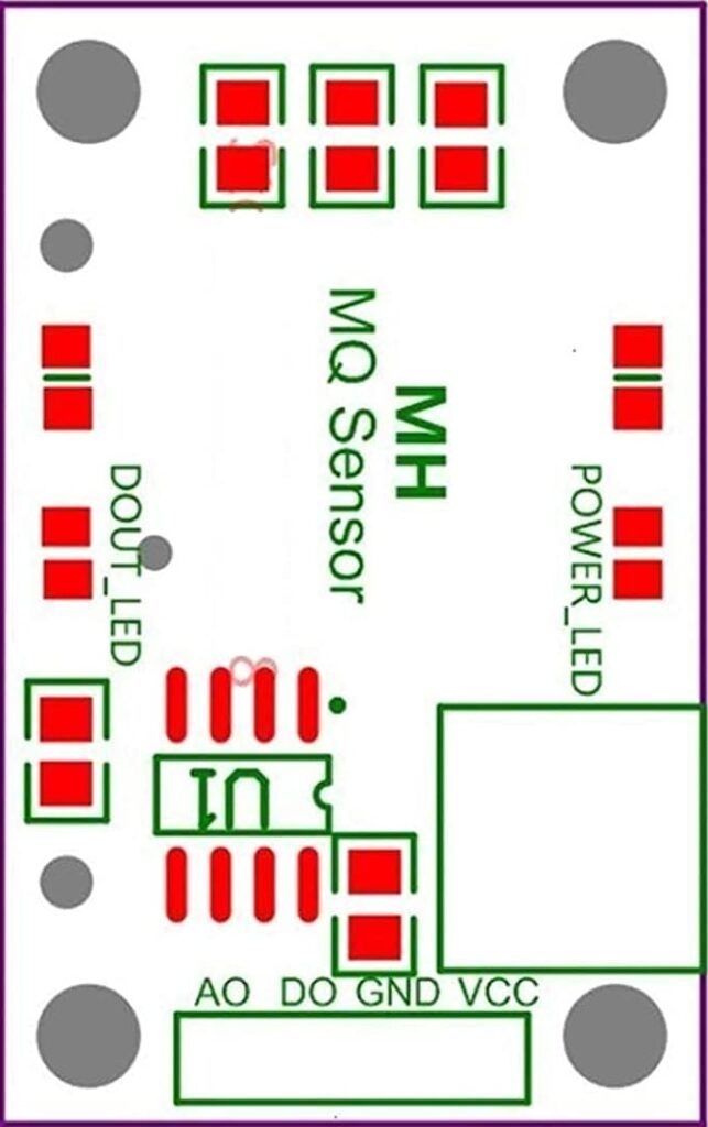
Next is the sensor. Again, link the jumper leads to the Arduino and the breadboard, aligned with the pins on the sensor:
- Sensor DO to Arduino D4 using yellow wire.
- Sensor VCC to Arduino 5V using red wire.
- Sensor GND to Arduino GND using green wire.
To get a better look at these pins, you can see them labeled at the bottom on the diagram below.

For now, that is the hardware done. Note that while you can still attach the +ve terminal of a 9 volt battery to the Vin (Voltage IN) socket in the ‘POWER’ section of your Arduino, you’ve used both power GNDs. However, it is possible to rewire this so you can make it portable. This is where the power rails on your breadboard come in handy. Try using one GND socket on your Arduino for your battery, and experiment using a power rail to add both the green and black wires to the other GND socket. Welcome to the world of electronics prototyping.
Stage 3: The Software
Now you’re ready to upload your code, so connect your Arduino to your computer and open the Arduino IDE software. If you need more information on this, visit the information in the previous ‘Let’s Talk Tech’ project. Type in the following, then compile and transfer to your Arduino. It will run automatically.
int buzzer = 8;     // Store the buzzer socket number
int co_sensor = 4;  // Store the sensor socket number
int co_detected;    // Define the flag for CO.

void setup()     // setup files
{
  Serial.begin(9600);    // Start comms with components
  pinMode(buzzer, OUTPUT);
  pinMode(co_sensor, INPUT);
}

void loop()     // Our routine
{
  co_detected = digitalRead(co_sensor);
  if (co_detected == LOW)     // Note the == compares it to 'LOW'
  {
    Serial.println("CO detected! Take action.");
    digitalWrite(buzzer, HIGH);
  }
  else
  {
    Serial.println("No CO detected. stay cool");
    digitalWrite(buzzer, LOW);
  }
  delay(200);
}
Did you type it in, or did you copy and paste it? Hmm, thought so. It’s worth typing in code by hand. You will learn to avoid the common syntax errors, like not capitalising the right letter, or omitting a space. Whatever language you code in, the devil is in the detail. If you couldn’t even be bothered to copy and paste, you can get the source code here.
Let’s test it. Try holding a burning matchstick up to the sensor. In this configuration, this is quite a simple detector; A binary, ON/OFF switch. However, you can fine-tune the sensitivity threshold using the manual adjustment on the sensor itself.
Focus on the pictured blue block. Using a small screwdriver, you can turn the grey bit left or right. Keep testing until you are getting the sensitivity you want. If you find it’s alarming more than it should, you must get your environment properly checked out for possible carbon monoxide leaks urgently.

If you want a stretch exercise then you can use the Analogue Output (AO) pin on the sensor, rather than the Digital Output (DO) pin. To read this you’d need to change the code and connect the AO pin to one of the analogue (A) sockets on the Arduino. Here is an example of some code you can adapt that would allow you to see the analogue results direct from the sensor. See if you can embed it into your existing code:
void loop()
{
  int sensorValue = analogueRead(A0);  // read the input on analogue pin 0
  serial.println(sensorValue);    // print out the value you read
  delay(1);    // delay in between reads
}
Despite all this, I doubt that many ghost hunts include checking the environment for carbon monoxide. I mean, who would want some party pooper explaining away your sense of ill foreboding, and scary visions and creaks, as something normal? Worse than that, you’d probably have to cut everybody’s vigil short for their own safety. That said, given the choice between a horrible death while having a great ghost hunt, and spending £40 on a detector just to be a bore, I know what I’d choose.
What are we learning? you might have realised that it’s a little more than how to be a better ghost hunter. Consider the practical skills in tinkering, programming and electronics that you’re developing. And unlike the classroom, we’re blending our knowledge of chemistry, biology, physics and technology to create something useful in the real world. This is called ‘engineering’. Welcome to the wider world, and SAFE ghost hunting.
- Schneider, Franz. “An Investigation of a “Haunted” House.” Science, vol. 37, no. 958, 1913, pp. 711–12. JSTOR, http://www.jstor.org/stable/1636744. ↩︎